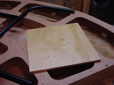
 Here they are over the pipe legs. I've not mounted the legs to the table yet.
I bought a 10' length of 1" PVC pipe, a 1/4" threaded rod, two 1" pipe caps, some 1/4" washers and some 1/4" nuts. I also bought some threaded adjustable feet.

I locked the caps in the drill press and drilled a 3/8" hole in the center. This will be for the adjustable foot.

Here is the pipe cap and foot assembly on the end of the pipe leg. Perfect fit! I did not glue the cap to the leg yet...this is still a test.
 I suspected that the legs would be a bit wobbly, but they were not. So I began to plan to put the legs on the section.
 Using some 1/4" plywood stock, I cut out a 12" x 12" square for the base plate for the legs.
I laid the square on the center radial of the module, 7" from the edge. This allows for the legs to be as close to the middle of the section as they can be and still be folded up so that they don't extend past the edge of the section. I marked around the square to keep the position and to indicate where I need to put the supports and glue.

I forgot to take a picture, but before I glued this plate down I cut 4 each 2" x 2" pieces of wood, 3" long. These blocks are glued in place under the corners to add strength and support, and to allow for anchoring the plate to the section.

The square plate was screwed on to the section with 4 each 2" drywall screws. The screws went into the blocks underneath. It did not wobble when anchored.
 Using 1 1/4" drywall screws I anchored all of the hinges to the square. The leg mechanisms are stiff and hard to move. I used a little WD-40 to loosen them up. Next time I'll only put four screws in (one on each hinge foot) and test the mechanism to see if I have warped it in any way, then anchor it down completely.
I tested the mechanism. It appears to work fine. Just a little tight. Getting it closed was a bit of a chore, but it will loosen up with time.

The first test of the leg assemble was excellent! My only issue was that it was a bit taller (by design) than I wanted. I removed the legs and took 2 1/2" off the pipe. This makes the benchwork height 48" to the top of the section. Perfect. Feels good.

Using a 2"x 2" board I made a kick leg to use when I'm setting up the sections (there is only one leg set per section, so they need each other in order to stand) or when I just want to work on/display one single section. This leg will clamp in place and can be easily removed.

You won't believe this, but I tested the module. It was PERFECTLY level in every direction and very sturdy. I was shocked. Marie heard me shout and came to see what I was working on. The height is just right for me and I like the feel of the layout already.
Great work tonight! This design is a go, so I'll buy another length of pipe, some more caps and feet. We'll finish the other legs tomorrow and fasten the whole layout together. Then I'll find out if fat Scott can get in the pit!
The rod and nuts? Oh, forgot to tell you. I thought I might put a cross bar between the two PVC leg segments in order to better stabilize it. This does not appear necessary so we'll not do that step. If I find that I'm having stability issues, then I will give it a try.


Scott,
ReplyDeleteVery nice - and easy (the perfect twosome).
Rick
A little yellow paint on the caboose handrails would set it off nice.
ReplyDeleteMax, Weona Railroad
I like the idea of yellow paint. We'll do that. I'm thinking a ladder to the roofwalk as well. Let's see what we can do to make it look realistic.
ReplyDelete